How to Install a Monitor Arm: Clamp, Grommet, VESA
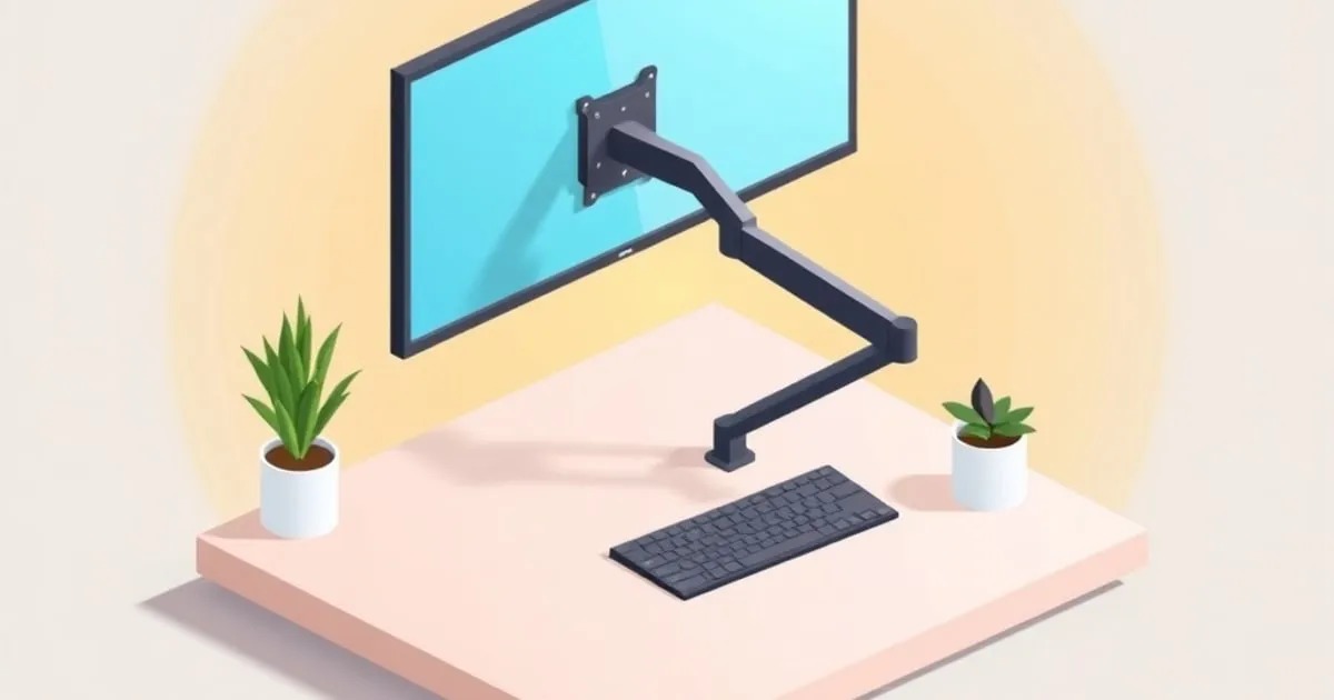
Install a monitor arm in the right order: check the desk, fit the clamp or grommet base, attach the VESA plate, hang the panel, then tension the lift.
A monitor arm install goes wrong in one of two places: at the desk, because the base was never going to fit, or at the spring, because the lift was never tensioned for the panel actually hanging on it. Neither failure shows up in the first five minutes. Both show up a week later as a screen that has quietly sunk two inches or a clamp that has bedded into the desktop and gone loose.
The order below follows the sequence manufacturer assembly guides use, and it exists for a reason. Every step is easier while the monitor is still off the arm.
Before You Open the Box: Three Checks
Three numbers decide whether the arm in front of you can be installed at all, and all three are knowable before the box is opened.
Desk thickness and edge access. A C-clamp needs a clear, flat, unobstructed strip of desk edge and a desktop inside its published thickness window. Ergotron’s published figures for the LX are a clamp rated for edges roughly 0.4 to 2.4 inches thick, and a grommet option rated for holes 0.31 to 2 inches across. A desk pushed flush to a wall, a desk with a rear cable channel running along the back edge, or a sit-stand frame with a crossbar under the mounting point all defeat the clamp before you start. The three attachment styles, their thickness limits, and when each one is the wrong choice are laid out in desk clamp vs grommet vs wall mount.
Panel weight without the stand. Not the shipping weight, and not the weight with the factory base attached. Published bare-panel figures for the common sizes are collected in monitor weight by size, and the reason both ends of an arm’s rating bind is explained in monitor arm weight capacity and the 1.5x rule.
VESA pattern and screw size. Measure the hole spacing on the back of the panel center to center. The 75 by 75 mm and 100 by 100 mm patterns take M4 screws; the 200 mm patterns move up to M6, sometimes M8. Panels with no holes at all need an adapter, covered in how to mount a monitor without VESA holes, and the pattern families themselves in VESA compatibility explained.
The Monitor Arm Fit Checker runs all three checks at once and returns a PASS, CAUTION, or FAIL per dimension with the spec reason attached. Run it before you cut tape on the box, not after.
For details on the 100x100 pattern and M4 screws, check the spacing separately from the screw length required by your monitor.
If the arm fails these compatibility checks, use the monitor arm ranking to compare replacements before continuing.
Tools and Parts
Most arms ship with everything except the tools: a base, a vertical post, the arm assembly, a VESA bracket or quick-release plate, a bag of M4 and M6 screws in two or three lengths, spacers for recessed VESA holes, and one or two hex keys. Beyond the box you want a Phillips screwdriver, an adjustable wrench for the grommet nut, a tape measure, and a second pair of hands for anything above roughly 20 pounds.
Lay the small hardware out before starting. A frequent assembly complaint is a screw a few millimeters too long bottoming out inside a monitor’s VESA boss, which happens because the correct short screw was still in the bag.
Step 1: Decide Clamp or Grommet, Then Position the Base
Do this while the desk is clear, because the base position determines everything downstream.
For a clamp, the post sits at the rear edge. Slide the clamp under the desktop, seat the top pad flat, and center the post on the sightline the monitor will occupy. Tighten until the clamp is firm against the underside, then stop. Overtightening a C-clamp on a laminate or bamboo top crushes the core and gives you a mount that feels solid on day one and loose by week three.
For a grommet, the post bolts through a hole with a plate above and below. Reuse an existing cable grommet if it sits within a few inches of where the arm needs to be. It is generally the more rigid of the two, because the load runs straight down through the desktop instead of pinching an edge, and it leaves more knee room.
Two positioning rules apply either way. Set the post far enough from the wall that the arm can retract fully, and set it so the monitor ends up directly in front of the seated user. OSHA’s workstation guidance is specific that the screen belongs no more than about 35 degrees off-axis, and a base bolted 10 inches off-center makes that geometry impossible no matter how much reach the arm has.
Step 2: Assemble the Post and Arm
Drop the post into the base, then slide the arm assembly onto the post. Most designs use a collar or a set screw at the top of the post to stop the arm lifting off.
Set the arm’s height on the post now, not later. That collar position sets the floor of the arm’s vertical range, and moving it afterwards usually means taking the monitor back off. Leave the cable covers and clips off for now; they snap on last, after routing.
Step 3: Attach the VESA Bracket to the Monitor
Lay the monitor face down on something soft. If the factory stand has to come off first, support the panel while releasing it; many stands are under spring tension and drop the panel when freed.
Match the bracket orientation to the pattern before touching a screw. A 100 by 100 mm bracket fitted 90 degrees out will still bolt up on a square pattern and will put the quick-release tab in the wrong place. Rectangular patterns such as 200 by 100 mm only go on one way.
Use the shortest screws that engage fully. If the VESA holes are recessed behind a curved back, that is what the supplied spacers are for. Tighten in a cross pattern, snug rather than forced. A stripped VESA boss in a plastic back is not repairable.
Step 4: Hang the Monitor
Push the arm to roughly the middle of its vertical travel before hanging anything. A spring joint at the very top or bottom of its range is harder to control with a load suddenly applied.
Lift the panel onto the arm’s mount, engage the quick-release or slide-on bracket, and then confirm the retaining screw or latch is actually locked. That retaining screw is the single most skipped step on the whole install, and it is the difference between a bracket that holds and one that lets the monitor lift off when the arm is tilted.
Keep one hand on the panel. The arm has not been tensioned yet, so it will either sink or shoot upward the moment it takes the weight.
Step 5: Tension the Lift Joint
This is the step that separates an arm that works from an arm that gets returned.
Every spring arm has a lift-strength screw, usually a recessed hex socket at the elbow or in the lift housing, marked with a plus and minus or an up and down arrow. Ergotron’s assembly documentation gives the procedure directly:
- Adjust with the monitor mounted. Tensioning a bare arm calibrates it for nothing.
- Raise the arm to mid-travel first. Some joints refuse adjustment at the extremes.
- Clockwise increases lift strength, counter-clockwise decreases it.
- Expect to keep turning. The guides warn plainly that depending on the product and the adjustment it may take many turns to notice a difference. Ten to twenty full turns is normal on a badly mismatched load, and a quarter turn producing no visible change is not evidence of a defective arm.
- Test the full range every few turns. The target is motion that moves smoothly through the whole travel and stays where it is put.
- On a dual arm, balance both sides. Uneven lift strength reads as one screen drooping.
Two safety notes appear in the manuals and are worth repeating. These mechanisms carry a stored energy hazard whether or not a monitor is fitted, so a lift joint is never something to open up. And on a heavy panel, support the screen with one hand while adjusting, because a spring released under an over-tensioned setting snaps the arm upward hard.
If the arm still will not hold after full adjustment, the load is outside the arm’s range rather than mis-tensioned, and the diagnosis tree in monitor arm drifting or sagging sorts out which joint is actually at fault.
Step 6: Set the Height, Tilt, and Distance
Now position the screen against real numbers rather than by eye. OSHA’s computer workstation guidance puts the top of the screen at or slightly below eye level, the screen center 15 to 20 degrees below horizontal, and the panel 20 to 40 inches from the eyes with no more than 10 to 20 degrees of tilt.
Sit in your normal working posture first, then move the arm to meet you. The full set of target measurements, including what changes for bifocals, ultrawides, and dual setups, is in monitor height and screen position.
Set it once and tension for that position. An arm re-adjusted daily is an arm that will need re-tensioning constantly.
Step 7: Route the Cables
Run the display cable and power lead along the arm’s channels with slack at every joint, then snap the covers on. Slack matters more than tidiness: a cable pulled taut across the elbow becomes the thing that limits the arm’s reach.
Then test the full range with everything connected. Full extension, full retraction, both height extremes, and portrait rotation if the panel will ever be rotated. Anything that snags shows up here, not later.
The Mistakes That Cause Most Reinstalls
- Clamping to a desk the arm was never rated for. Glass tops, hollow-core doors, and thin floating desks all fail differently, and none of them fail immediately.
- Skipping the retaining screw on the VESA quick-release.
- Tensioning before mounting the panel, which calibrates the spring for nothing.
- Positioning the base for cable convenience instead of for where the screen has to end up.
- Not re-checking the clamp after two weeks. Laminate beds in. One re-torque and it stays put.
- Never re-tensioning after a hardware change. The manuals are explicit that the adjustment steps repeat whenever mounted weight changes, and a webcam or light bar counts.
Dual and Triple Installs
The sequence is the same, with one addition: balance the two sides before final tensioning, because a single-post dual arm concentrates both panels’ torque on one clamp. Geometry, spacing, and the asymmetric-load problem are covered in the dual monitor setup guide, and the point at which two singles beat one dual arm is in single vs dual vs triple monitor arm selection.
If the Arm Does Not Fit the Desk
An arm that cannot be installed is not a defective arm. The usual outs, in order of cost: switch from clamp to grommet using the hardware already in the box, add a reinforcement plate to spread the load on a soft desktop, or move to an arm whose published clamp range covers your desktop. The Ergotron LX (Amazon Associates) ships both clamp and grommet hardware together, which is why it survives desk changes that send single-mount arms back.
Related Reading
- Desk clamp vs grommet vs wall mount — choosing the base before you buy
- VESA compatibility explained — patterns, screw sizes, and adapters
- Monitor arm drifting or sagging — when tensioning does not hold
- Monitor height and screen position — the numbers to set the arm to
- How to choose a monitor arm — getting the specs right before install day
Final Word
Check the desk, the panel weight, and the VESA pattern before anything comes out of the box. Mount the base, hang the panel, then tension the spring with the real load on it and keep turning past the point where you expect a change. Everything that goes wrong later with a monitor arm traces back to one of those steps being skipped.
Sources
- Ergotron WorkFit-A Dual — Assembly Instructions (tension adjustment after a load change)
- Ergotron LX Desk Dual Direct Arm User's Guide (lift-strength adjustment, stored energy hazard)
- Ergotron LX Desk Mount LCD Arm — Published Clamp and Grommet Dimensions
- OSHA Computer Workstations eTool — Monitors
- VESA Flat Display Mounting Interface Standards (MIS-D/E/F patterns and screw sizes)
Related

Desk Clamp vs Grommet vs Wall Mount: How Monitor Arms Attach
The three ways a monitor arm attaches to your desk — C-clamp, grommet, and wall mount — compared on install effort, sturdiness, and thickness limits.

What Is VESA Mount 100x100? Pattern, Screws, and Fit
What is VESA mount 100x100: the 100 mm hole spacing, the M4 screw spec, how to confirm your monitor has it, and why the pattern says nothing about weight.

VESA Compatibility Explained: Mount Patterns and Adapters
This guide explains VESA mount patterns, arm compatibility, adapter options, screw fit, and the checks needed before installing a monitor arm.